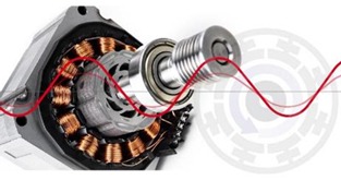
Figure 1: The PMSM is a brushless DC motor that requires a sinusoidal waveform for commutation
Although it requires a more complex waveform, the PMSM benefits from lower torque ripple and reduced audible noise. For this reason, it is often the preferred motor type in applications requiring smooth and quiet motion, such as high-end home appliances, power tools, and industrial automation.
Historically, sine-wave commutation has been handled using algorithms implemented in microcontroller unit (MCU) firmware that require extensive optimisation and fine-tuning to work with the chosen motor and meet the requirements of the application. Also, the MCU’s performance must be adequate to execute the control algorithm up to the maximum required speed while also handling application-level processing.
Position sensing and soft-start
Unlike a brushed motor, where simply applying power will ensure the correct coils are engaged to start the motor satisfactorily regardless of where the rotor last stopped, starting and running a BLDC motor requires knowledge of the current rotor position. This is needed to allow the appropriate coils to be excited and the rotor to begin rotating in the correct direction. Sensors are often fitted to brushless motors to detect this position. Alternatively, a sensorless setup saves on the expense and the potential reliability issues associated with sensors (such as Hall devices).
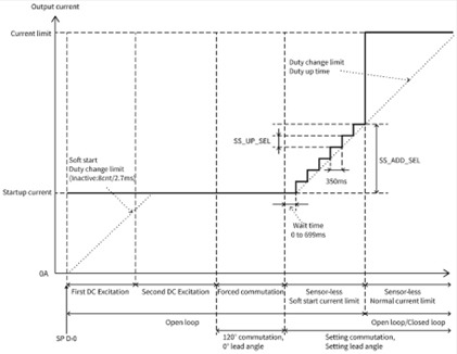
In this case, techniques are needed to move the stationary rotor in a known starting position before energising the coils. Without proper precautions, the rotor and anything attached to it could whip back in the wrong direction.
When the coils are energised, this must be undertaken in a manner that prevents PWM switching from generating excessive noise and vibration during the time where no useable back-EMF is available to determine the rotor angle. In essence, the motor control algorithm is driving the motor blind. Once sufficient back-EMF is available, the motor controller can switch to the chosen control method.
Fine-tuning the drive
The ability to start the motor and select the speed, however, is only a subset of the functions needed to operate properly. The motor-drive designer must have the flexibility to integrate the controller with MOSFETs of a suitable voltage and power rating for the application. They also require the ability to optimise parameters (such as acceleration, lead angle, and PWM frequency) to ensure the system will respond as required to the user’s inputs and maximise energy efficiency in all operating conditions.
Achieving MCU-less control
The Toshiba TC78B011FTG sine wave pre-driver relieves any need for an MCU. This parameterizable chip for sensorless three-phase brushless motor control is a pulse-width modulated (PWM) chopper that can be connected to external low-side and high-side N-channel MOSFETs, allowing for a scalable inverter implementation to match a range of different motors.
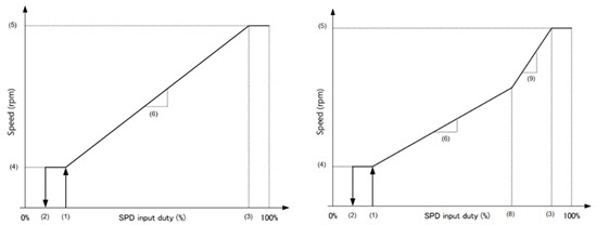
While the device provides open-loop speed control, closed-loop control that maintains the target speed unaffected by power supply or load variations, with an adjustable speed curve, is a more typical requirement. This can be achieved by configuring the precise operating mode via the I2C interface, with the option to store the settings in a non-volatile memory (NVM). Hence, suitable settings can be programmed during manufacture for circuits that do not use a microcontroller or processor.
On the other hand, the motor speed can be adjusted by writing to a register through the device’s I2C interface and can also be determined using either a PWM input or an analogue signal. Braking and direction, also, are controlled via register settings or external pins. The motor current and rotation speed can be read from external pins while the motor is running.
More accurate positioning
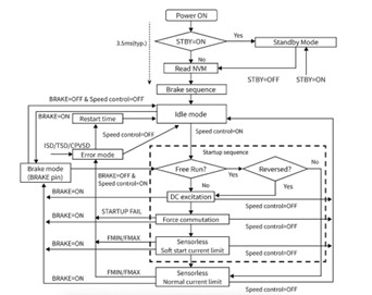
After powering-on, the TC78B011FTG retrieves the stored device configuration from its NVM (see Figure 2). At this point, a brake sequence may be applied by shorting the appropriate coils through the motor inverter to ensure that the rotor is stationary before attempting to start rotation. Once the initialisation sequence is complete, after around 3.5ms, the driver enters idle mode with all MOSFETs turned off and awaits further instruction from the host system.